
In this post, I will lay out the basics on how to blink a LED on barebone Atmega328P. This means no arduino bootloader, some datasheet reading, and a more solid understanding of the basics when done. As usual, the code, along with a practical Makefile, is available on github. The latest version is on the master branch, and is discussed in the next part.
Here are the basics you will need to follow along. Not everything is a hard requirement, and with a bit of creativity you can avoid some of those parts, but this kit is a safe bet to get you going with the most basic features of an AVR microcontroller:
Now that all pieces are around, let's wire it up.
Here's the pinout of the Atmega328P, straight from the datasheet:
The clock is generated using an external crystal oscillator. The connections are pretty straightforward, see "Crystal Oscillator Connections" in the datasheet.
Connect the reset pin to VCC via the 10k resistor, and to the ground via the push button. Remember to leave some space for the RESET pin of the programmer.
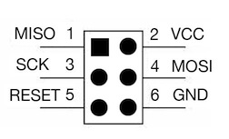
The 6 pins of the ISP (In System Programming) cable (VCC, ground, MISO, MOSI, SCK and RESET) go to the corresponding pins2 on the microcontroller.
Connect the VCC and AVCC pins of the microcontroller to the power (at this point it can simply be provided by the programmer), and the two ground pins to the programmer's ground. If you have a ~1uF capacitor laying around, put it with a small resistor between VCC and ground, to stabilize the power.
Connect the LED from any free PIN (I chose PC3) to the ground, via a ~1k resistor.
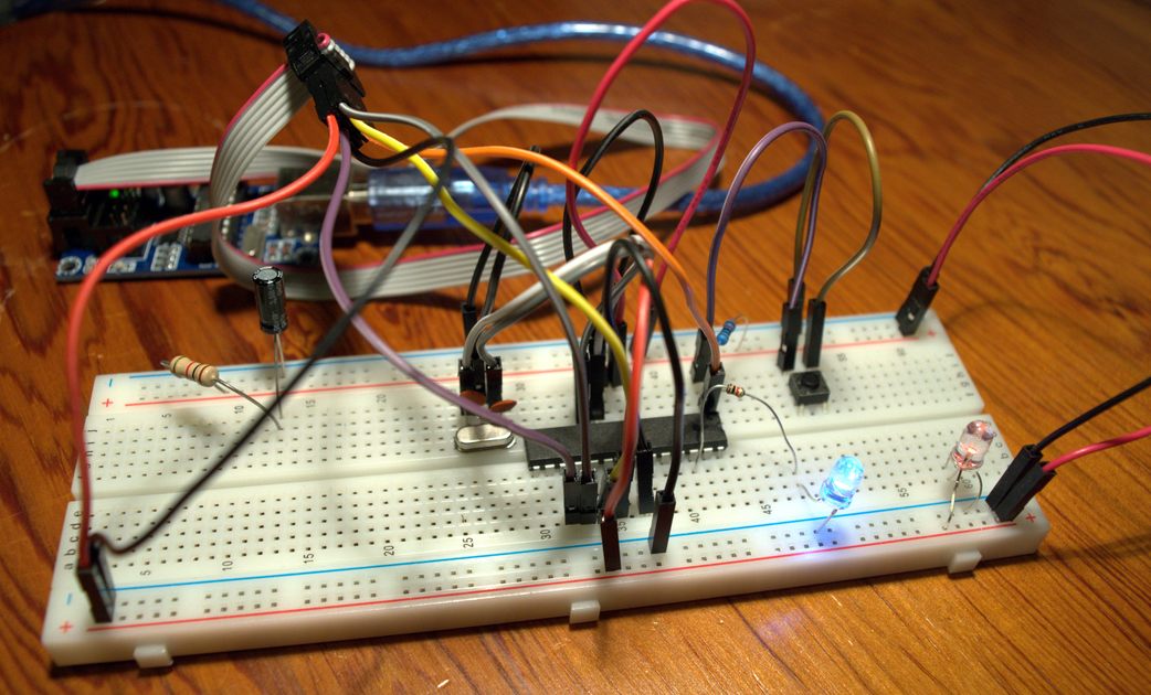
With this basic wiring in place, you're now ready to program your first LED-blinker.
If you're unsure about some connections, try to find it in the datasheet. Understanding its structure and being able to look stuff up on your own will save you a tremendous amount of time.
avrdude needs to know what programmer and microcontroller you have, and what to upload. The command to upload (in verbose mode) myfile.hex to an Atmega328P, with an USBTinyISP programmer, looks like this3:
avrdude -v -p m328p -c usbtiny -U flash:w:myfile.hex
To get a list of supported parts, type avrdude -p '?', and avrdude -c '?' for a list of programmers.
We're able to upload programming file! Let's write some lines that blink a LED.
Doing IO on digital pins is straightforward: writing to a global value defined in <avr/io.h> will pass it down to the IO registers, effectively setting the pin high or low. You will also need to set its mode to input or output.
#define F_CPU 16000000UL        // Speed of the microprocessor, in hertz (16 MHz)
#include <avr/io.h>             // provides PORT* and DDR* registers
#include <util/delay.h>         // provides _delay_ms(), and needs F_CPU

int main()
{
    // set the DataDirectionRegister of PC3 as input
    DDRC |= _BV(DDC3);

    while(1)
    {
        // set PC3 on
        PORTC |= _BV(PC3);

        // caveat: the precision falls down after 260 ms
        // see the avr-libc documentation
        _delay_ms(250);

        // set PC3 off
        PORTC &= ~_BV(PC3);

        _delay_ms(250);
    }

    return 0;
}
If you're confused with the various bitwise operators (|, & and ~), just remember that we use it to read or write one bit at a time. The PC3 is the bit number.
To compile, substitute your own microcontroller version:
avr-gcc -Os -mmcu=atmega328p -c -o main.o main.c
avr-gcc -Os -mmcu=atmega328p -o main.elf main.o
avr-objcopy -O ihex -R .eeprom main.elf main.hex
Upload (substitute your programmer and microcontroller too)
avrdude -v -p m328p -c usbtiny -U flash:w:main.hex
You will see the LED blink, but only once every ~4s, whereas we expected it to blink twice a second!
This is because the default, out-of-factory state of your microcontroller is to use an internal 1 MHz clock source, instead of the external 16 MHz oscillator. The F_CPU value used in utils/delays.h to compute the time per instruction is then wrong. Let's fix that!
By looking under the "Clock sources" section of the datasheet, we guess that the "Full Swing Crystal Oscillator" is what we want. A paragraph later and we learn that we should set the fuses CKSEL[3:1] to 011. We must also set CKDIV8 to 1 to disable the clock division.
Conveniently, those fuses are all set in the low fuse byte (see the MEMPROG section). First, let's read the current values to double check our assumptions:
avrdude -v -p m328p -c usbtiny -U lfuse:r:my_low_fuse.raw:r
This will create a 1 byte file containing the current lfuse value, in my case 0x62, or 0b01100010. To correctly set CKSEL and CKDIV8, we will switch the first and sixth bit (starting from the left!), and get 0b11100110 (which is 0xe6 in hex). We can now write it to the microcontroller:
avrdude -v -p m328p -c usbtiny -U lfuse:w:e6:m
After resetting the board, we see that the LED now blinks twice each second!
This concludes the first part of this series. Next up: debug printing with an UART.
The crystal is external, but the clock source is still internal. ↩
The pinout is an upper view, assuming that the red wire is on the side of the MISO and VCC pin. ↩
If avrdude dies with 'Warning: cannot open USB device: Permission denied', you can either launch it as root (and suffer the consequences) or write a udev rule matching your programmer vendor and device id. ↩